


Gap Adjustment of Conical Rotor 3-phase Asynchronous Motor
1. Structural drawing of conical motor (fig 1)

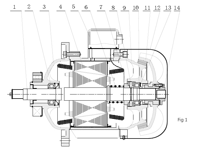
6压力弹簧Pressure spring 7支承圈Support ring 8平面轴承Plain bearing 9后端盖End Cap
10后轴承Rear bearing 11风扇制动轮Brake Fan 12风罩Fan cover 13调整垫片Adjusting gasket 14、锁紧螺母Lock nut
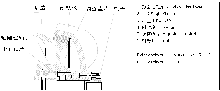
2 The assembly of lock nut, brake fan and end cap is as follows (fig2)

Ensure the axial assembly accuracy (the axis of stator and rotor coincides) and the thickness of air gap gasket (the stator and rotor do not rub each other), so as to ensure the uniform air gap between the motor stator and rotor. Motor air gap“ δ” And air gap gasket is shown in the fig
Motor frame number is different, motor air gap is different“ δ” It is also different. The bigger the frame number is, the smaller the air gap is“ δ” The bigger it is.
Enlarged view of air gap gasket
Fig 3
(1) generally, the air gap gasket shall not exceed three pieces.
(2) the air gap gasket is placed between the bearing and the oil seal.
4 Motor shaft extension H (fig3)
(1) motor shaft extension “H” is the front cover plane
The dimension to the top of the shaft.
(2) the tolerance of shaft extension “H” is ± 1.5㎜
5 Schematic diagram of rotor assembly
1轴 roller 2 短圆柱轴承 Short cylindrical bearing 3 前油封Front oil seal 4 压力弹簧Pressure spring 5 支承圈Support ring 6 卡簧 Snap ring
(1) in the drawing of short cylindrical bearing, only the inner ring is drawn, and the outer ring of bearing is on the end cap assembly.
(2) there are two sets of short cylindrical bearings on each motor. When assembling, the inner and outer rings of thefront and rear bearings must not be matched wrong. If the matching is wrong, the assembly quality will be affected, and the motor will be noisy and not flexible.
6 Schematic diagram of front cover assembly
1 前端盖 front cover
2 短圆柱轴承 Short cylindrical bearing
3 孔用挡圈 Retaining ring for hole
7. Brake clearance adjustmentThe brake clearance has been adjusted during the factory test of the motor,during the use of the motor, with the wear of the brake ring, it is necessary to check the brake every month and adjust the brake if the brake is not smooth.
There is no standard for brake adjustment of conical rotor motor. When the motor is running, the brake is fully opened and the brake can be quickly stopped when the power is off!
It is suggested that the clearance is 3mm in our factory.
arrange mode
After the motor is powered off, remove the rear windshield and you can see an 8-hole lock nut with 4 adjusting bolts; Use a hammer to tap around the lock nut. After tapping the lock nut gently, adjust the four adjusting bolts to tighten the brake counterclockwise and loosen the brake clockwise
The best clearance between brake fan and brake seat ( ≤7.5kw is internal brake which has a end cap used as brake seat; ≥11kw is external brake which the fan cover used as the brake seat) is 3mm.
conical motor spacing adjustmentconical motor spacing adjustment